


Broadcast Applicance
The delivery of audio and visual material over electronic communication channels such as radio, television, and the internet is known as broadcasting. Broadcast devices are communication systems that employ radio transmitters and receivers to provide numerous programs to listeners.
Encoders, IRD, ASI IP converters, RF Distribution, and more are all available.
Encoders, IRD, ASI IP converters, RF Distribution, and more are all available.
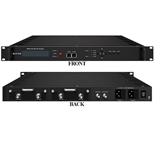

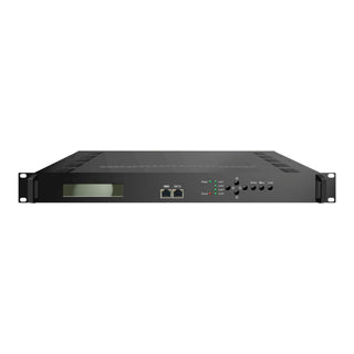
4ch SDI to IP MUX MPEG2 or H264 Encoder
$2,495.00
$4,995.00
Usually delivered in under 2 weeks
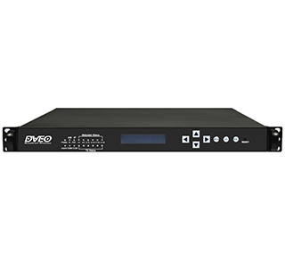

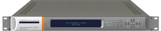
1 RU Modulator Gateway with Redundant Power Supplies, and Redundant Gigabit (Gig/E) Inputs
$495.00
$1,995.00
Usually delivered in under 2 weeks
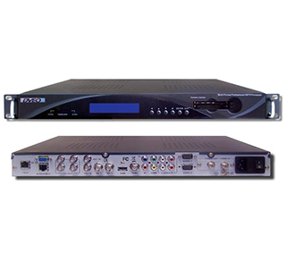

The T-Ramp™ IP+DVB-S-S2+ASI/SDI+HDMI+ASI+IP is an advanced MPEG-2 and H.264.
$495.00
$1,995.00
Usually delivered in under 2 weeks


The T-Ramp™ IP+DVB-S-S2+ASI/SDI+HDMI+ASI+IP is an advanced MPEG-2 and H.264.
$2,595.00
Usually delivered in under 2 weeks
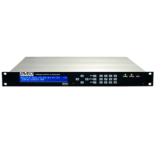

MPEG-2/4/H.264 Decoder & Frequency Agile Satellite Receiver That Demodulates All Satellite Frequencies & Decodes.
$495.00
$1,495.00
Usually delivered in under 2 weeks

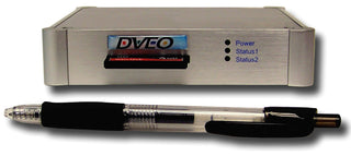
4ch Analog to IP MUX MPEG2 or H264 Encoder
Contact us for pricing
Usually delivered in under 2 weeks

Cost Effective, Super Reliable, MPEG-2 or H.264 Repeating Transport Stream Playout or Clip Server with ASI Playout.
$1,295.00
Usually delivered in under 2 weeks
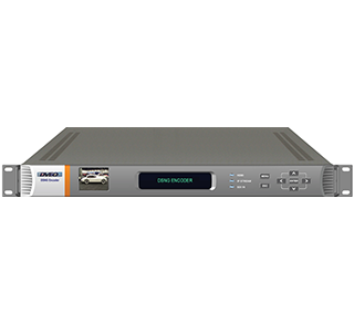

1080p SD or HD 4:2:0 & 4:2:2 MPEG-2 & H.264 DSNG Contribution Encoder with Built in Satellite Modulator.
$4,995.00
$7,995.00
Usually delivered in under 2 weeks
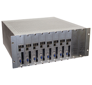

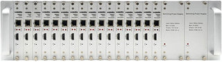
Professional, 4 RU, High Density, Modular, Blade Based IRD Receiver with Dual CAM Slot Support.
$10,995.00
Usually delivered in under 2 weeks

The Furano is 422 ATSC, DVB-S/S2, DVBC receiver decoder
$995.00
$1,995.00
Usually delivered in under 2 weeks

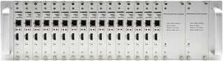
HDMI AVC/H.264 audio & video HD live encoder with 16 HDMI inputs & 16 IP outputs.
$3,495.00
$7,995.00
Usually delivered in under 2 weeks

HDMI AVC/H.264 audio & video HD live encoder with 4 HDMI inputs & 4 IP outputs.
$495.00
$1,495.00
Usually delivered in under 2 weeks
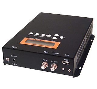

Single HDMI or Analog to QAM/DVB-C Modulator with integrated MPEG-2 & H.264 Encoder with 1080/720p over coax.
$1,095.00
Usually delivered in under 2 weeks
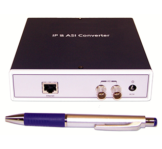

ASI to IP or IP to ASI Converter for Bidirectional SPTS or MPTS Transport Streams over High Speed IP Backbones.
$795.00
$1,495.00
Usually delivered in under 2 weeks
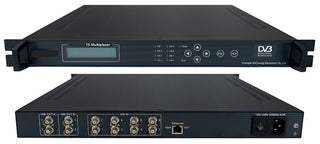

TELCO Grade, hardware based, 1 RU, Real Time, MPEG-2 Transport Stream Multiplexer with ASI in & ASI out.
$495.00
$1,995.00
Usually delivered in under 2 weeks